One of my least favorite but also most favorite things to work on is PCB layout. It’s a dull, mundane, and unglorious task, but at the same time it’s perfect for getting into a flow state and zoning out with a podcast or music. When I’m in that zone, a whole day goes by in a blink and I’m not paying attention to anyone or anything around me. One summer day that’s where I was, doing some layout for a prototype. It was a busy day in the office, we had summer interns, and they were helping an engineer with an oscillation problem and looking through a circuit, and one of the interns said “Oh right, the gain is R1/R2 plus 1. That’s so weird how flipping the signs adds a 1”.
Cue record scratch. I was immediately ripped from my slumber. The gain of an op-amp is -R1/R2 if the input goes into the negative terminal, and it magically becomes R1/R2+1 if the input goes straight to the positive terminal. And the negative feedback does all this. As if the op-amp and the concept of negative feedback and these simple equations were handed down on stone tablets in the mid-20th century.
The reason the intern said this and why most EEs are either terrified or clumsy with op-amps is that they’re taught in such a way that you simply have to accept a couple formulas in order to pass the exam.
What I’d like to do here is present op-amps from their perspective, the game they’re playing. If you only know op-amps through the lens of a couple equations, the second you step even slightly outside those equations you’re completely lost. I mean, what does “-R1/R2” tell you about noise or bandwidth? The real way to understand op-amps is to go inside one and try to design one and really get to the working principles and gears and guts. That takes years to do, so instead as a compromise I’m going to present a way to think about op-amps that give you real working intuition based on their inner operating principles without having to actually cut open an IC. Before we go any further, here is my nephew preventing me from leaving for the airport.

An op-amp is thought of as a 3-terminal device, but it’s really a 5-terminal device. The terminals are:
- Positive Input
- Negative Input
- Output
- Positive Power Supply
- Negative Power Supply
An op-amp doesn’t *grab* the inputs and shoot out bigger versions of them, it’s not a magical amplification device. Energy can’t come from nowhere. What the op-amp is really doing is precisely controlling current from the power supply based on what the inputs tell it, while letting the power supply and inputs be unaffected by each other, providing isolation. It’d be like if an old grandma needs to get something off a shelf in her kitchen, so she asks her tall grandson to get it for her. The grandma isn’t physically doing it, but she’s the one saying what to do. The grandson isn’t thinking about it, but he has the physical ability. Op-amps facilitate this interaction.
To illustrate that op-amps aren’t magical components, below is what’s inside an LM101, as shown in Prof. Roberge’s book available for free on MIT OCW “Operational Amplifiers: Theory and Practice”
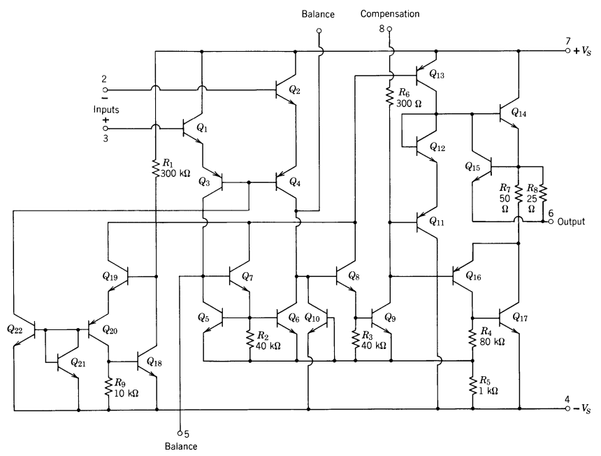
This one component, an LM101, which you can buy in a little DIP package, actually has a dozens of components integrated together in it. The more complex ones have hundreds of components. Look at it for a little bit — don’t stare too long though, let’s get back to the normal world. What I’m trying to say is that op-amps have a ton of stuff inside of them, they’re not just a triangle you draw on paper. Being mindful of that can help understand what’s going on and why we have the shortcuts that we do.
Op-amps have two input terminals. Inside the op-amp, the transistors are engaged in a tug of war. There are two input transistors, and they share one current source. Just like in a game of tug-of-war, even though you’re trying to pull the person over the middle, you’re also trying to not fall. If the rope slips a bit because you pulled too hard or the other side fakes you, you fall, and then it’s over. The input transistors are trying to share the current source, but pull *sliiiiightly* more, just slightly more, enough to win over time.
This is the magic behind negative feedback. When the input voltages are really different, the transistors — pulling the rope — go wooaahhhh woah woah hold on and try to get their footing again and try to get it back to an equilibrium. Not because the inputs don’t matter, those transistors do want to win, but they don’t want to lose, so it’s better to keep the inputs nearly equal.
In tug-of-war you have ways of knowing what’s happening. Your nerves on your fingers and palms, your eyes, your ears, natural sensors that provide feedback. Electronics don’t have that. We need to give electronics some way to know whether their output matches their intention. They want to multiply the inputs by 10, how do they know whether or not they did that?
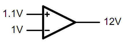
Let’s take this amplifier stage and strip away everything and build it back up. We have two input terminals, and one output terminals. We now know that those two inputs need to be really close to equal to keep the tug of war happy. They don’t need to be equal, in fact they shouldn’t be equal, they need to be sort of equal. Equal-ish. How can we let the inputs know that they’re doing the right thing? If they don’t have any feedback, they’ll just shoot to infinity! When one input transistor has a higher voltage, it’ll just yank on that rope until the output hits the rail. In the case below, the positive terminal is slightly higher than the negative, it pulls the rope so the output hits the high rail of 12V.
How do we make them do what we want them to do? We talked about negative feedback and how it’s easier to drive with your eyes open (according to the Massachusetts Department of Transportation), but op-amps don’t have eyes or ears or fingers. They only have voltages.
So let’s start there. Voltages. What can we do with them? The simplest circuit I can think of is a voltage divider. Let’s put a voltage divider on the output. We could measure the output, write it down, and then adjust the input. Or just…directly tie that voltage divider back to the input and make it all happen automatically.
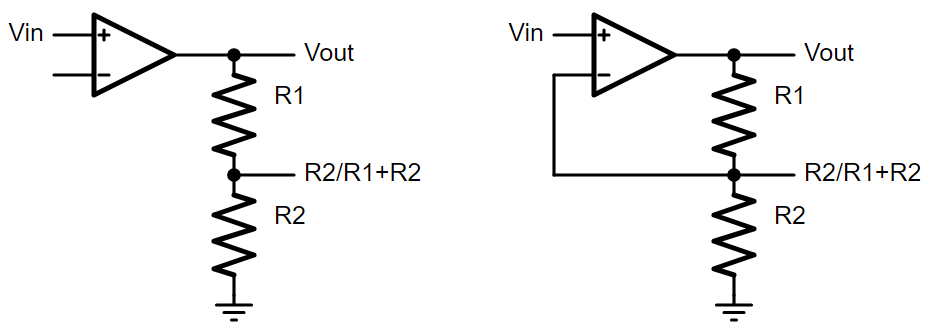
The positive terminal will initially be higher than the negative, so Vout will quickly go up. But at a certain point, the output of the voltage divider will be almost exactly equal to the input voltage, therefore keeping the input terminals almost equal. The tug of war finds a happy equilibrium in this, and Vout settles to its final value.
What is its final value? Well if the negative input terminal is the voltage coming out of the voltage divider, then Vout must simply be the inverse of that, right? As an example, if R1 and R2 are equal to each other, the voltage divider is half of Vout. Intuitively, it’s obvious that Vout is therefore double whatever voltage is at the voltage divider. Because of the tug of war happening within the op-amp, the voltage divider is almost equal to Vin, which means Vout is double Vin. This lines up with the equation you may know for the non-inverting op-amp, 1+R1/R2.
Let’s generalize and formalize it a bit. That voltage divider ratio, we’re going to call it the “feedback factor”, and we’ll assign it variable beta. From what we just saw, the gain of the amplifier must therefore be the inverse of that. What’s great about this is that the feedback factor can be anything. It can have capacitors, making the gain variable with frequency. It can be the output of a current sensing resistor, which allows the op-amp to precisely control current.
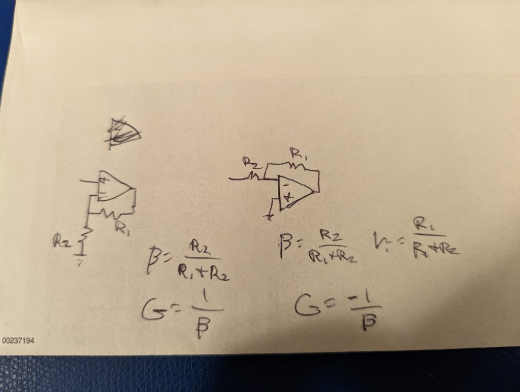
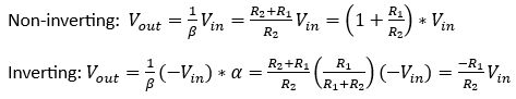
Let’s get back to what what intern said. Why is it that in the inverting configuration, the gain is -R1/R2, but with the non-inverting it’s 1+R1/R2? Looking at the back of the envelope drawing above, you can see that both circuits have the same feedback factor. The difference is that with the inverting configuration, the input also has a feed*forward* factor, which will be denoted alpha. See, with the non-inverting, the input voltage is wired directly to the positive terminal. With the inverting configuration, if you look, you’ll notice that the op-amp isn’t actually seeing the input voltage. It’s seeing the input voltage divided down by R1 and R2. That’s what the op-amp is providing gain to. From this perspective it makes sense right? The equations below illustrate this.
An interesting side effect that comes out of this is that for a given gain, inverting op-amps are noisier. I’ll leave it to the reader to figure out why.
Once you start thinking about op-amp gain in terms of feedback factor, it becomes significantly easier to design more complex circuits with them without having to write out lengthy KVL/KCL equations.
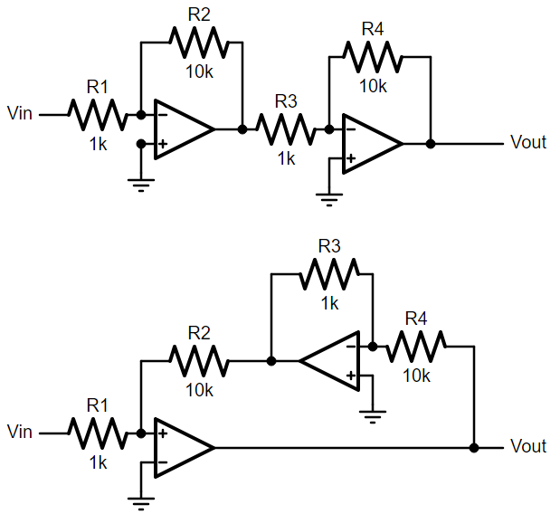
The circuits above show a clever use of feedback factor to improve the amplifier. The first circuit is called a cascaded amplifier. Two amplifier blocks, each with a gain of -10, so the overall gain is (-10)*(-10)=100. Pretty simple. But by understanding feedback factor, we can reconfigure it to the second circuit. From a network theory perspective, these two circuits are actually completely equivalent if you write out the mesh network matrix, but we can avoid that by thinking about the feedback factor. Two things to note, the first op-amp now has feedback going to its positive terminal instead of negative. This is still negative feedback because the second op-amp already has a negative gain. R3 and R4 are swapped, so rather than a gain of 10, it actually has a gain of 1/10th. What this does is it divides the first op-amp’s feedback factor by another factor of 10, and therefore makes its overall gain 100 rather than 10.
This seems pointless and needlessly complicated, which it is if the op-amps are ideal, but for non-ideal op-amps it provides a lot of neat benefits that are beyond the scope of this post. For a more detailed explanation of this circuit, and more advanced network theory concepts from a self-professed wonk, see Prof. Shanthi Pavan’s lecture series on Modified Nodal Analysis.
By thinking about circuits in terms of feedback factor, you truly unlock the power of op-amps as a tool for precise control of anything you desire. Motor speed, temperature, power, frequency generators, filters, whatever it may be. Below is one of my favorite circuits, called a biquad state variable filter. It gets you a lowpass, bandpass, and highpass filter all in one go, and you can independently set its sharpness with the upper op-amp. If you get an op-amp package with four op-amps, you can do it all in one small component. It looks really scary, don’t worry we won’t go into the analysis of this one, but if you look closely you can break it down into blocks, and see the feedback factor of each.

For further reading, I highly recommend this 9-part article series from All About Circuits about Negative Feedback.

Love how your cat made it into the blog, lol. 🙂
LikeLiked by 1 person