A friend of mine who had taken a circuits class asked me this and at first I was confused. He took a whole circuits class, half of it was spent on resistors. And then I realized it’s honestly a really good question. They’re presented as a scribble on a chalkboard with no context, you do some math, you get the answer. Who cares? But really what is a resistor? What do they represent? How do we use them? Why do we solve these resistor networks in college classes that you would practically never see in real life?
This post is for people starting their electrical engineering journey and need some context for what to look forward to, as well as non-electrical people who sometimes interface with circuits and would like to know how and why this ubiquitous component is used.
A resistor is any device or model where changing the voltage by one amount means that the current will change proportionally by the exact same amount at the same time. And vice versa, so changing the current means the voltage across it will also change. It operates by a simple equation, Ohm’s Law. V=IR, where R is the resistance, I is the current through it, and V is the resulting voltage drop across it. The essence of what’s occurring is that electromagnetic energy, provided by the voltage source, is causing the electrons to — on average — move slightly more in one direction. First off, for electrons to move, they have to be detached from any one specific atom. Electrons like staying with protons, opposites attract. In some materials like metals, the electrons are all like leaves in the wind and just need a gentle push. In others, it takes a bit more energy to get them going. As electrons move, they collide with each other, and they collide with all the atoms. This is kinetic energy and releases heat. Electromagnetic energy is converted to kinetic energy which is converted to thermal energy. Sweet.

Notice I said “device or model”. Let’s first focus on “device”, the capital R Resistor, that many of you are probably already familiar with.
Resistors (the device)
You can go to a website like Digikey or Mouser or your local electronics store and buy a component called a Resistor. You can find them in a variety of shapes and sizes, surface mount, through-hole, chassis mounted. You can sort them by their resistance, by their tolerance, by how much power they can dissipate etc and them put them into a circuit to do something. They look something like the pictures below.

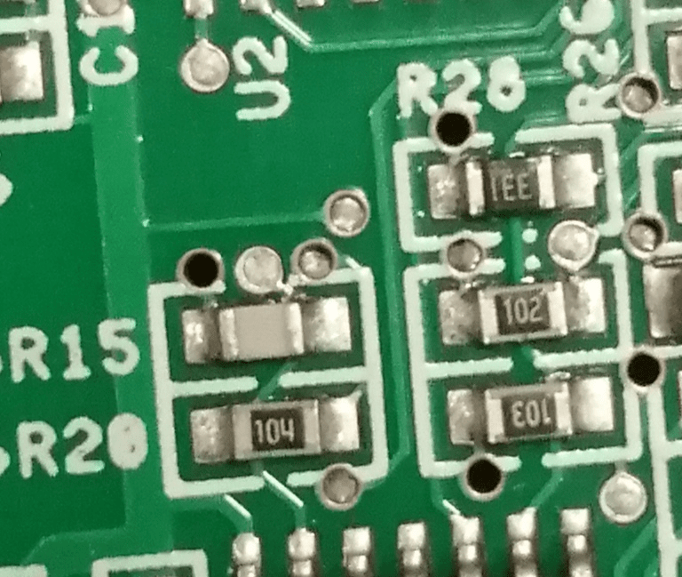
The board will be marked with “R” and then a designator number, and the part itself will have markings that let you know what resistance it is. Resistors as a device, whether we’re talking about polysilicon fractions of a micrometer long in a chip, or massive hunks of metal that can dissipate thousands of Watts installed in high power substations on the electrical grid, are purposely manufactured and designed by engineers for specific reasons. Let’s dive into some of those reasons.
Current Limiting
The reason resistors are called resistors is because they resist current. Say you have a device that can put out 15V. It’s only expected to put out a few milliamps, but that device will explode if it puts out more than 500mA. So we put a resistor on that output to limit the maximum equal to 15V/500mA = 30R (since the Omega symbol doesn’t come standard on an English keyboard we just suffix it with R if it’s in the single digits). Resistors are manufactured on a logarithmic scale, so we’ll pick 33R since that’s a commonly made value. Going a little higher than what we wanted benefits us because then it keeps the current slightly below the absolute maximum.
The Load below is 1kOhms, but it’s entirely possible for it to get shorted to ground, or be hooked up improperly by the user. The Current-Limit resistor prevents this situation from blowing up the op-amp.

Voltage Divider
This is a pretty simple one. Electricity and circuits can be thought of like water, where batteries are pumps, voltage is like height, and current is…well, current. Think about a water slide, where it starts off at a height, and the water flows down until it reaches ground, where it’s then pumped back up to the top. Circuits work similarly. Now let’s say that instead of a smooth slope down, we get multiple jumps down, like waterfalls. Those drops are like resistors. With every one of those drops, the water itself *loses* potential energy. In the same way, every resistor in a circuit drops voltage.

Maybe you have a battery or some voltage source that gives you a higher voltage than you need. A voltage divider can give you a lower voltage than what you’re given, and then you can use that voltage for whatever you need. You can use multiple resistors to give you multiple voltages, multiple access points from the same source.
Now why would we want to divide or drop the voltage? Sometimes it’s used to do something called “biasing”. Transistors are controlled by the voltage at their gate (or base) and we can use a voltage divider to set the operating point of the transistor, which then determines how it works as an amplifier. See my previous post on designing a single-stage BJT amplifier for an example, where the voltage divider Rb1 and Rb2 set the BJT’s operating characteristics.
Another major use is feedback, which we’ll explore further down.
Current Sense
In most situations, we as humans have control of voltage, and we control things based on voltage. We mostly work in the domain of voltage and that’s the quantity that’s of interest to us. But current is the more “real” and “tangible” physical value, and is also often something we’re trying to control or sense.
Maybe we’re sending power to something, but we know that if we send too much current it’ll overheat. So we use a resistor to *convert* that current to a voltage a la Ohm’s Law, and then we can use that voltage to shut down the output and keep the device from overheating.
As an example, this chip is the LTC4361. It senses current and then switches power on or off if the current goes too high. The diagram below, taken from its datasheet, shows how you’d use the LTC4361 in a circuit.

This circuit allows for a USB power supply or a wall adapter to power or charge the Load. The MOSFET M1 (Si470DH) acts as a switch between the power source and load. Current goes from left to right, but whether or not current can go left to right through M1 is based on the voltage coming from the Gate and Out pins on the LTC4361 across M1. Rsense is a current sensing resistor. It converts the current into a voltage, which the LTC4361 can use to actually make a decision based on its internal logic. If the voltage across Rsense gets too high, the chip shuts off M1 so no more current can flow to the Load.
Transimpedance
A lot of devices that sense light, like a photodiode, produce a current. The light energy comes in photons, and those photons knock electrons, which get pushed out and that makes a current. But again, we often can’t do much with current in terms of information. If we put a resistor at the end of it, the current will go through the resistor and *create* a voltage, just like the current sense, which we can then use to do stuff.

The concept of transimpedance is most commonly used in amplifiers. Again, using the example of the single-stage amplifier covered in a previous post, Rc plays an important role. See, transistors are called transistors because they’re “transconductance resistors”. “Transconductance” is a fancy word for “converts voltage to current”. So the input to the transistor, the voltage at the base created by the voltage divider and Vin, controls the current coming down through the transistor Q4. But as I’ve mentioned multiple times here, what we want is voltage. We want to take a voltage input and get an amplified voltage output. That current goes through Rc, and it converts the current into a voltage. Transimpedance.

In this topology, known as an emitter degenerated amplifier, Re also helps turn voltage to current, sort of “programming” the current in a way.
Programming Current
The circuit below, provided in “Microelectronics” by Sedra and Smith, is known as a current mirror. Q1 is a MOSFET that’s in a configuration we call “diode connected”. It acts in a predictable way. VDD is, ideally, a constant value. Using this predictable behavior, we can pick a value for R that “programs” a current of our choosing to down through Q1.

Now here’s where the magic happens. There is a direct relationship between the voltage at the gate of a MOSFET and the current going through it. Usually we control the voltage to get a current. But in this case we’re doing the opposite. We program a current using R, and that produces a voltage at the gate. Notice that the gate of Q2 is connected directly to Q1, so they have the same gate voltage. And because the gate voltage to drain current relationship is the same, that means Q2 will have the same current going through it. So by setting a value for R, we can send whatever current we want out to another section of the circuit.
Feedback
Voltage dividers and current sensing resistors are really mostly about this. Feedback. It wouldn’t be a stretch to say that feedback is one of the most important concepts to understand. If you can master feedback you can master most of electronics and honestly most engineering.
Your body is a highly complex feedback system. It releases hormones that control your metabolism based on various biochemical reactions in your digestive system. You produce sweat based on the temperature outside, but then the sweat evaporates and cools you down, so your body produces less sweat because it doesn’t want to *over*cool you. This is why marathon runners are given blankets when they reach the finish line; their body has been sweating and pumping out heat while running for hours on end, and when they suddenly stop it takes a bit for their body to stop cooling itself to the point that it can actually cause hypothermia.

The concept of feedback is rather simple: A) I want to do a thing B) I do a thing C) I want to make sure I did the thing I wanted to do in the first place. I can adjust Step A and B based on Step C, the feedback component. It’s like when you play the game where you try to draw a face with your eyes closed and it looks like a Picasso painting, but not in a good way.
You may have built a device where you can send it a command, and it will output a certain current. You send a command that says “OUT 25” and it will output 25mA. But how does the device know it output 25mA? Without feedback it has no way of knowing. Maybe it actually put out 30mA. Maybe it put out 100mA. Even if it put out 25mA exactly, it could drift over time because of temperature or humidity and there’s no way it could correct it.
That’s why voltage dividers and current sensing resistors are important. When we decide “this input should create this output”, feedback is the method that guarantees the system will work that way.
Here’s an example of an electronic feedback system. Let’s say there’s an LED we want to turn on. Maybe it’s not just a regular little LED that indicates the device is on, and the brightness doesn’t really matter, but instead it’s an LED laser that needs to be very precisely controlled.

The light blue is the input control path. The op-amp then applies a voltage to the MOSFET, M1. That pulls a current through the LED laser, D1, then M1, and down through Rsense. Rsense is a current sensing resistor, producing a small voltage based on the output current. That voltage is then fed back to the negative input. The op-amp, U1, is happy when its + and – inputs are equal to each other, so it adjusts the control voltage to the MOSFET until the green line is equal to Vin! If Vin is 10mV, then U1 will control M1 so the voltage across Rsense is also 10mV. By Ohm’s law, 10mV/100mOhms = 100mA. So if Vin is 10mV, we get a precise 100mA going through the LED laser!
NB: this is why tolerances on resistors are important. Ideally, Rsense is exactly 100mOhms, but in reality it will be slightly higher or lower, which means you’ll get a different current going through the LED. If you see a circuit with a resistor that specifies 0.1% tolerance, that means it’s part of a feedback loop that requires tight control.
Filtering
Electromagnetic waves of every frequency are all around us all the time. The lights in your room are electromagnetic waves. The heat coming off your body is electromagnetic waves. The reason you can sit in your seat, why you can walk around, what keeps the clothes on your body, is all electromagnetic energy.
But all of that stuff is so annoying when we’re trying to do something! We want our phone to get some signal from the 5G tower nearby, and there’s all this noise. On top of that, we want to only send and receive *our* signal. We don’t want to interfere with another person’s phone and we don’t want theirs to interfere with our’s. We can do this with filtering.
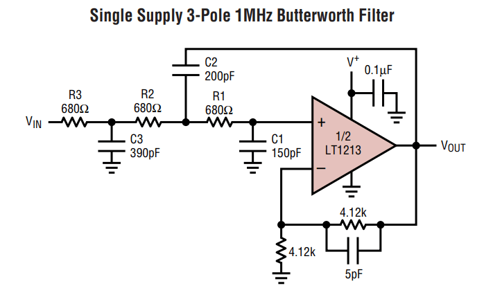
I won’t go into the mathematics or theory of it here, but an analog filter may look something like this, taken from the datasheet for an LT1213 op-amp. You use a *reactive* element like a capacitor or inductor, and a *resistive* element, and you can control which frequencies are allowed to pass through and which are blocked.
There’s entire books written on this topic. How and why different structures and values are chosen aren’t really important to understand here, but resistors are needed to create filters.
High-Speed Termination
As the digital world gets smaller and faster, we need to send signals at higher and higher frequencies. When the frequency gets up high enough, our fancy little tricks we use to simplify complex electromagnetic equations break down, and we have to revert to black magic. Some weeeird stuff starts happening at high frequencies. Wire become antennas. When we switch 1’s and 0’s several million times a second, it doesn’t look like a nice neat wave and things can get real funky looking.
So to help keep the signals nice looking, we put resistors somewhere on the line to smooth it over. Below are two popular methods of terminating high speed digital lines.

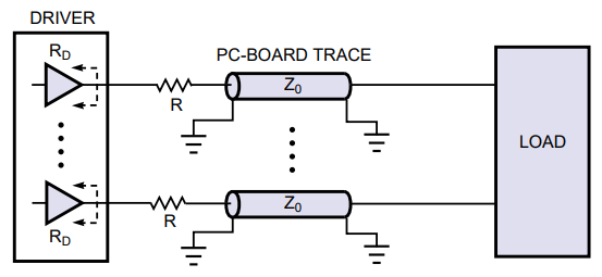
The part in the middle, Z, is what we call a transmission line, where the wire itself looks like a bunch of resistors, inductors, and capacitors all stringed together. In order to mitigate the oscillations and reflections and radio frequency nonsense that happens at high speeds, we add resistors in either configuration above.
Resistance (the model)
We now move on to the part that eludes a lot of beginners. The fact that resistance is not just a thing you buy off a catalog, but a concept that exists all around us.
Parasitics
Your body is a resistor. Water is a resistor — or at least water with some amount of salt in it. Things you don’t think of as resistors are resistors, because if you apply a certain voltage you’ll get a certain current. Our system might have components in it that we didn’t intend to put in there, but we need to analyze them exactly like the components we did intend to put in there so that we can design our system more accurately.

We think of wires as having no resistance, but they actually have some finite resistance, they’re made of physical material. When we pass a large enough current through them, the voltage drop can be significant. This comes in to play quite a bit in high power systems.
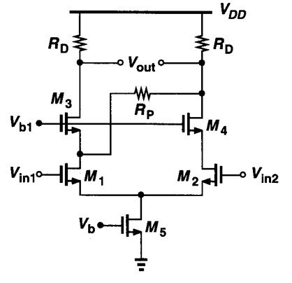
The above circuit is called a “cascode differential amplifier”, taken from “Design of Analog CMOS Integrated Circuits” by Behzad Razavi. “Differential” because there’s two inputs, Vin1 and Vin2, and “cascode” because each input transistor has a second transistor stacked on top of it. See those two resistors Rd? Those are transimpedance resistors just like in the BJT amplifier example above. Those resistors were purposely placed there and had their values chosen to get a specific output voltage or current. See Rp? Nobody purposely put that there. We don’t want it there. But it’s there anyways, maybe because of bad layout or because of a manufacturing defect. It doesn’t matter that we don’t want it there, it exists and now we must account for it.
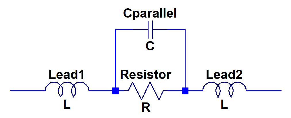
It goes the other way too. Resistors are devices that we buy because of their resistance, but there’s more than just resistance there. Resistors also have capacitance and inductance. If you were to break a resistor down into ideal resistance, capacitance, and inductance, it looks like this.
Sensors
Engineering is all about creative problem solving, and that can often mean taking a negative and turning it into a positive.
Normally when we put a resistor into a circuit, we want to keep it as steady as possible even when conditions like temperature or pressure change. What if by accident or incompetence we end up making a resistor that changes a lot with temperature? Well hey, maybe we can’t use it as a resistor like we want, to sense current or for feedback, but if we know the resistance changes with temperature in a determined way, we can use this to our advantage. We can send a current through it, as if it’s a current sensing resistor. But in this case, instead of a constant resistance and changing current producing a changing voltage, a changing resistance and constant current produce a changing voltage.
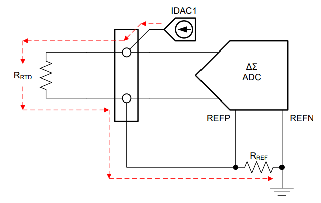
In the diagram above, IDAC1 produces a constant programmable current; that current goes through the RTD, a resistor that’s designed to change resistance linearly with temperature; by Ohms Law that current through the RTD produces a voltage; that voltage is read by the ADC which can be read by a computer and easily processed and displayed however we want.
Neat isn’t it?
Loads
With sensors, the resistance is part of our input. Other times we can model devices we’re sending outputting power to as a resistor as well. The most obvious example is a heater. Your space heater is nothing more than a big hunk of metal that looks like a resistor. Normally we think of losing heat as inefficient, but in this case we want to waste as much heat as possible, so that heat can make your house hot.
Those are the primary ways resistors are used or modeled in circuits. Hopefully this will help you when you’re looking at a circuit and wondering what the purpose of a certain resistor is, or learn when/how to implement them in a design.

Thanks for the great explanation! I was wondering—how does temperature affect a resistor’s resistance, and are there specific types of resistors that are more stable under temperature changes?
LikeLike
This is an excellent question. I started typing out a response but it got long and I realized more people might want to know so I will create a new post answering the topic of temperature and resistors.
LikeLike