Peripherals involved: SPI, UART, GPIO, TIM/PWM
So I have this evaluation board, the STM32F407G Discovery Kit. One of the peripherals on it is the LIS3DSH, a MEMS (Micro ElectroMechanical Systems) accelerometer.
The accelerometer is part of the reason I got this dev kit in the first place. I wanted to make a toy out of it, electronic drumsticks. The instrument, not the chicken wings. The idea was that you would place them on a surface, hit a calibration button, and then bang the device on the surface to make sounds like it was a drum. I’m not a drummer myself, but I am totally that person that just starts drumming on whatever table I can. This was supposed to be that.
Now it turns out it actually takes a decent amount of math and signal processing that I’m not yet ready to implement or am ready to sink the time into.
But shoot it took me days to properly get a calibrated output from this accelerometer, I wasn’t going to just drop it. I finally managed to get SPI communication working, calibration working, and UART output to my computer working. The result is here:

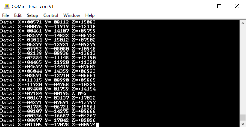
The first screenshot is my output every 500ms. 1g of downward acceleration is represented as 16,383 (0x3FF). The full range of the output is +/- 2g in 12-bits of representation. The first bit is lost to the sign, and then it’s again divided by 2 because the full range is 2g in either direction, so 1g is represented as 11 bits all on. The second screenshot is as it’s being rotated. You can see each axis changing quite a bit as I move it around.
Thinking about the next step from here, I decided I’m going to instead output a PWM to a few LED’s as proof of concept. The more I rotate the board in either direction, the brighter its respective LED gets. Below you can see the PWM duty cycle increase as I rotate the dev kit.
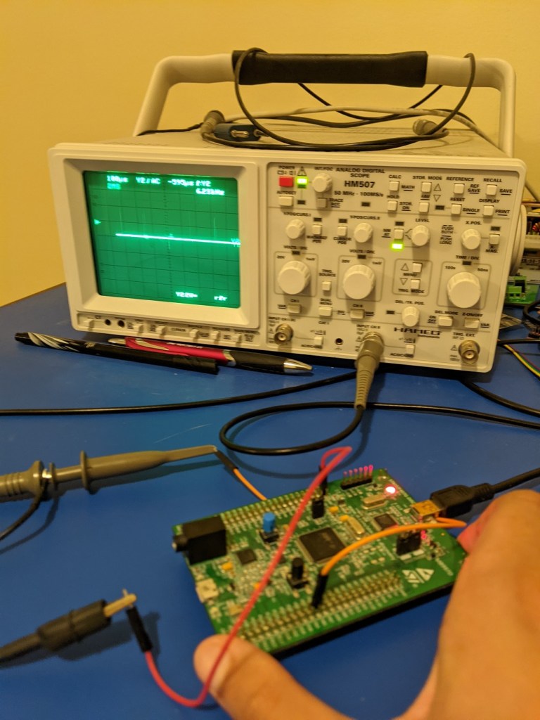

Now the PWM output is set. A 50% duty cycle wave runs at 1.25kHz. The period is 1000 clock cycles, so we can get 0.1% resolution on our LED output. That should be plenty. Next step is to make those LEDs shine! I’m making the decision to source the output directly from the board. I’m keeping the LEDs to a max of 7mA so as not to blow past the GPIO pin specs.
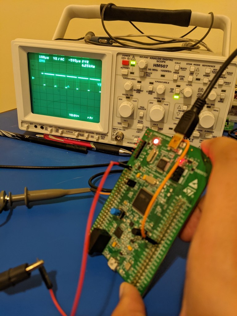
This is the system as I have it right now, moving it in either direction will increase the brightness on the LED as wanted. You might notice there’s some glitchiness here (glitchiness I will exploit in my next project). For one, a lot of the dynamic range happens towards the lower end of the duty cycle. The brightness increases logarithmically. Secondly, the accelerometer is being sampled at 1200Hz (max for the accelerometer), with no filtering of any kind.
The result is a bunch of flickering at the lower end of the spectrum. Worse than that, the noise keeps the LEDs bouncing back and forth. Notice how when the eval board is sitting there, *all* the LEDs are flickering to some degree. Remember, the LEDs are meant to represent axes of motion. When the joystick is rotated to the right, the left LED cannot be on, because the DC motor controlling the X-axis will only be able to rotate in one direction.
So changes to make are: a) do some averaging to reduce the flickering as well as filtering to make it tolerant to small taps and vibrations; b) create a deadband so none of the LEDs are on when the eval board is just sitting there at the origin; c) linearizing the rotation signal to duty cycle better to create a smoother sense of control.
