4/2/23 – It’s April 2023. All of summer 2022 went by where I tried forever just to get Sky130 set up, only to find out that it basically doesn’t work for analog design. My fall semester was torturously spent in RFIC, during which I invented a somewhat novel circuit at work and then left for a new job right before finals week. Yup, I started a new job two weeks while working on an RFIC term project and studying for finals. Suffice to say I haven’t had any time to just play around with some dang transistors in Cadence. And now that I’m doing a class in photonics while work gets ever more stressful, I long for the days of small signal analysis.
So here we go, let’s see if I remember anything from 2 years ago or whatever.
4/5/23 – Man am I out of practice. I forgot how to do even the basic stuff. I mean I remember all the keyboard shortcuts and how to setup Cadence and all that, but it took me a couple hours to properly size these things and get something reasonable. After much finagling, I found that the easiest thing to do was to simply set all the lengths equal. And for this go around, rather than deal with deep sub-micron design challenges, I just set the length of everything to 600nm. This is probably not a good value to use, especially when I have a feature length down to 65nm available, and seems like cheating, but I’ll save that for a future op-amp (maybe a telescopic one that has more transistors?)
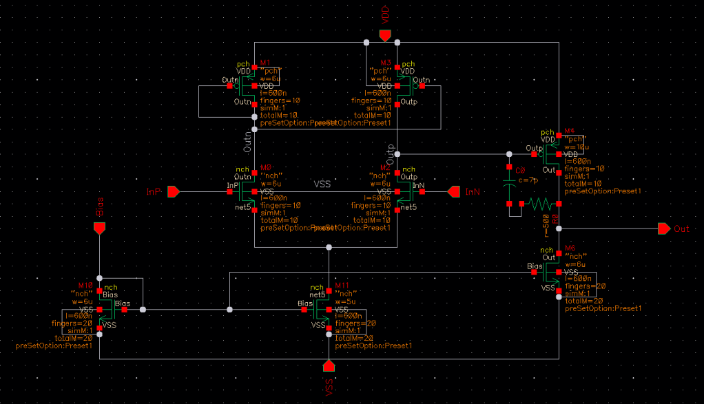
I designed it to get a gain above 60dB, so I went for a gain of ~40V/V per stage. Here’s the schematic I came up with.
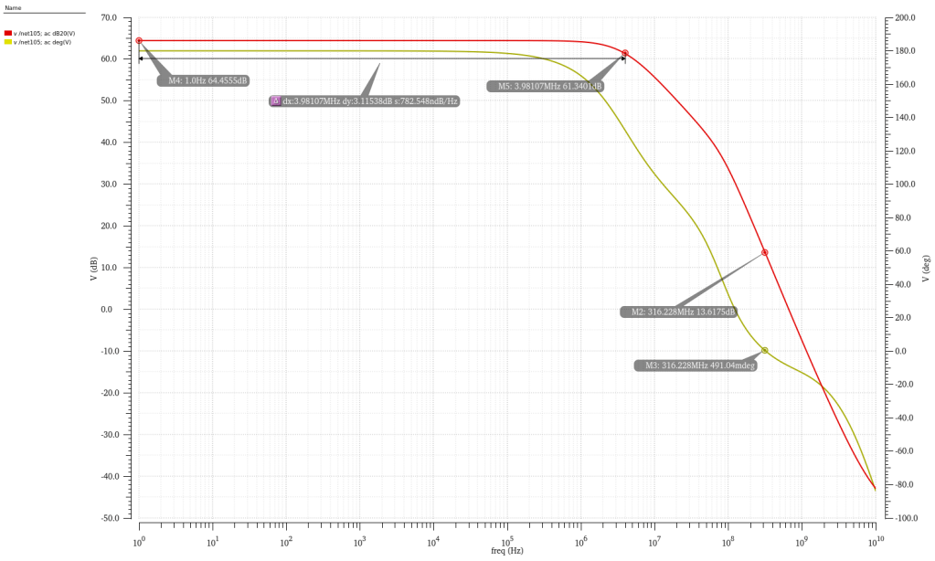
I feel like we have some good bones here for a basic op-amp. The gain is hitting above the target 60dB, and the power consumption is well below the 500uW I wanted. Good transient response, but the open-loop system (below) is unstable. You can see that the gain at the phase crossover is over 13dB. No bueno. Now I turn to Miller compensation to improve the stability of this op-amp. I’m gonna shoot for 45 degrees phase margin.
4/8/23 – This is the new frequency response after adding Miller compensation. As you can see, we now have a nice 47 degree phase margin, close to what we calculated. You can also see that the dominant pole has moved way down to 12.5kHz, putting unity gain at 25MHz, where there’s now a zero. But then just after the zero there’s a pole roughly at 150MHz. This zero is not predicted by Miller compensation, but it’s crucial to getting the phase shift to be what we want, and it moves the second pole higher up, which is called “pole splitting”.
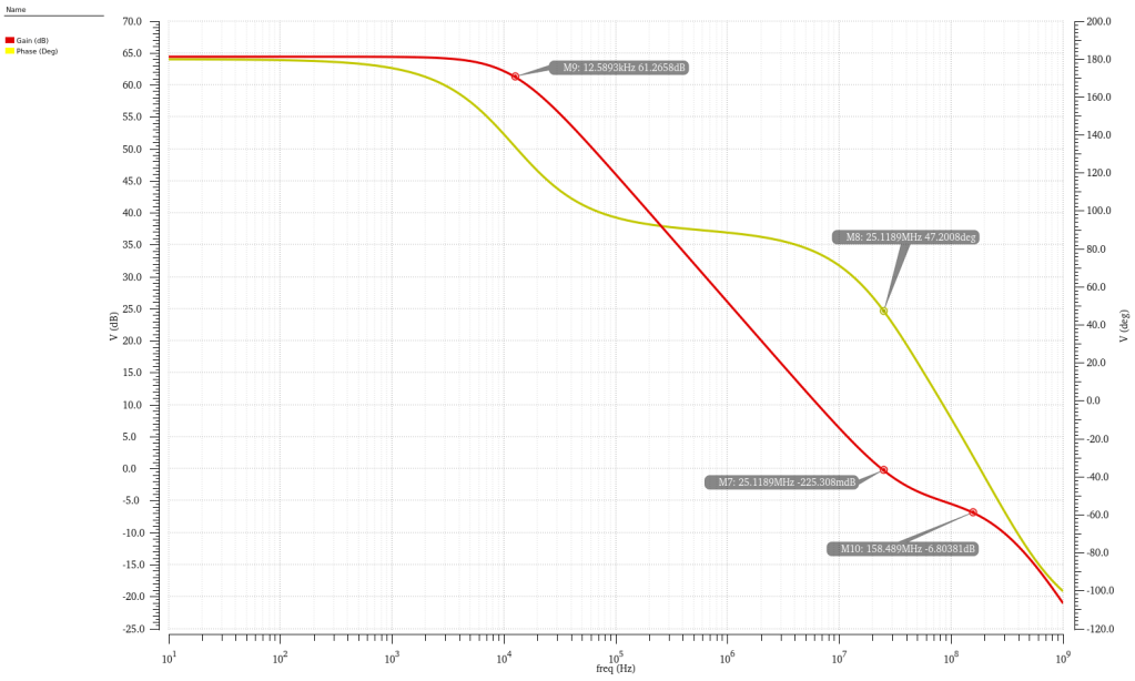
Something I’m not particularly a fan of though is the startup time of the circuit. The lower bandwidth means the DC output takes some settling time, in this case roughly 50us for a 100kHz signal.
4/10/23 – Next up, I throw this into a testbench and set up some more formal tests. I’d like to get an idea of things like harmonic distortion, noise, common-mode rejection etc. From what I hear, Cadence is pretty much discontinuing ADE and will only be updating/supporting ADE Explorer i.e Maestro from now on, so I better get used to it.
My initial results are thus:
| Parameter | Value |
| Power Consumption | 286.4uW |
| DC Gain | 64.4dB |
| -3dB | 12.5kHz |
| Gain Crossover | 25.1MHz |
| Phase Margin | 47 deg |
| CMRR | -73.7dB |
| PSRR | -72.8dB |
| Input referred noise | 649nV/rt(Hz) @10Hz, 66nV(rt(Hz) @1kHz |
| Non-linearity | -45.8dBc HD2, -54.3dBc HD3 |
As this is the first op-amp, a low transistor count, I’m going to try and use this as a general purpose one I can throw in multiple times where I don’t need high speed but could use that 65dB gain. The GBWP is 25MHz anyways which is handy. What that means is I need to decrease that power consumption. 286uW is okay for one circuit, but for 10 or 20 it’s not good at all. I’m going to try to reduce it to below 100uW, while keeping the gain above 55dB. Let’s see how long it takes before I give up.
Using the basic equation, if you hold the width constant and lower the length, you must lower the current as well to keep the same transconductance, which is what we want to do. As an added bonus, Vgs-Vth should remain constant as well, meaning we don’t affect our headroom. But this is assuming it follows the square law. Right now we’re using an L=0.6um, where the square law holds a bit more strongly. I’d like to take it down to ~200nm, where this will no longer be the case. I also have to be careful about stability, because changing the length means changing the system poles, so this may affect stability, but I’m not sure. The other thing is that decreasing the length means decreasing the output resistance, lowering the overall gain.
I’ll first set up a quick parametric sweep. I want to set up a transistor similar to the diff pair, 60u/600n with 100uA, and sweep the length down to 100nm and current down to 20uA and see what we get.
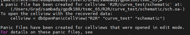
4/12/23 – Doing great. Today’s going great. Worked for 13 hours today plus 2 hours of class, and still going, and when I got the motivation to just set up a simple parametric sweep, it crashes over and over. Thank you Cadence, I’m sure a “panic file” is nothing to be worried about.
4/19/23 – Back up and running, the sweep gave me some not so nice answers. It’s true that decreasing the length means the W/L ratio goes up and thus so does the gm. But the gds goes up at a faster rate than gm, which leads to an overall reduction of gain. The intrinsic gain, gm/gds, seems to be related to length linearly. So counterintuitively, I actually have to *increase* the length to maintain gain.
N.B. – I can’t actually post any sweeps or anything like that, because I signed an NDA on this technology node.
I think what I’ll try here is reduce the bias current and keep the length where it is. That will reduce the gain of the differential stage, so what I’ll do is increase the W/L of the second stage slightly to compensate for it.
But then the issue I keep running into is that increasing the gain of the second stage greatly increases its power usage. It’s now past midnight here and I should get to bed, so I’ll leave this op-amp how it is for now and put this one in the portfolio. It’s not great, but not a bad first attempt. I didn’t get the power consumption below 100uW, but it’s at 150uW with a gain of 60dB, which is pretty good. The noise is marginally better, but the non-linearity is degraded. Phase margin somehow improved, it’s now 70 degrees, which is very stable.
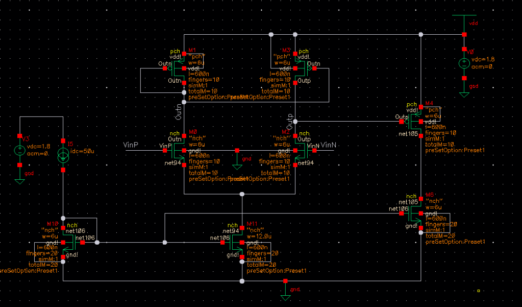
Overall I’m pleased with the results. I could do a lot better but I’m a bit tired at this point. Here’s the final schematic for reference: