One of the, if not the biggest hurdles to understanding transistor circuits — and system modeling — is small-signal analysis. As with all things, the reason it’s difficult to understand is that professors are given very little time to provide context, so it’s given or received like scripture on golden tablets in a language you’ve never heard of. I would say “it’s all Greek to me”, but I’m an engineer so half my notes are in Greek letters. It’s all….Amharic to me. Now that’s complex.

Small signals, big ideas
Before I clear up misconceptions about small-signal analysis, let me just say what the concept is in the first place. Can’t refute lies if you don’t have a truth to begin with.
Transistors are very complex structures that exploit semiconductor physics. They’re multi-dimensional creatures that can be understood in multiple ways and from multiple perspectives. At it’s basic core, it’s a device where charge across one pair of terminals controls current capacity through another pair of terminals. This is a super weird process, it’s very non-linear. We don’t like dealing with non-linear things because we don’t have a common language or mathematical method of dealing with them. They’re pretty icky.
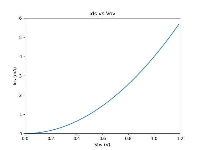
So we instead lie to ourselves and say “well hey what if we zoom into a tiiiiiny little part of it?” and say it’s close enough to a perfectly straight line. This is called linearization.
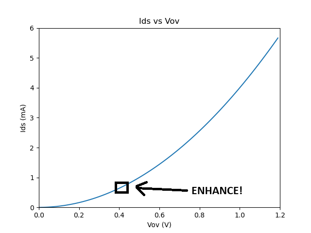
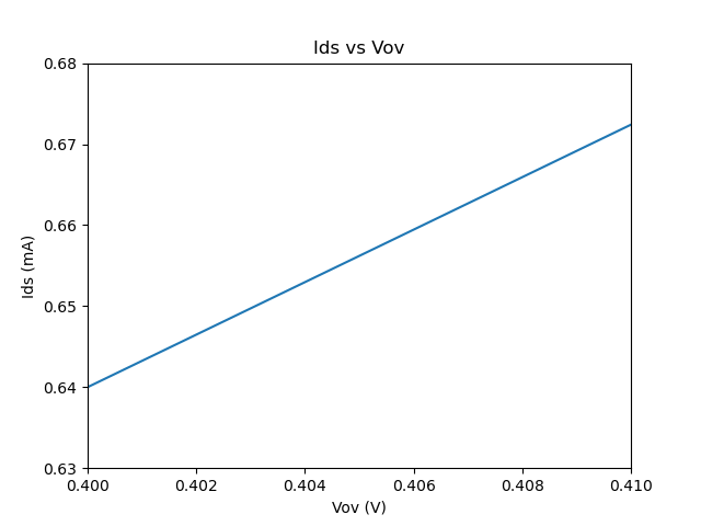
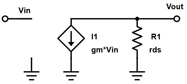
If we make an assumption that the transistor is operating only around that point, we can say it’s basically linear and it makes the math a dozen times easier. The transistor is a perfectly linear voltage-controlled current source, and the output is a linear combination of the input. Voltage to current, current to voltage. Easy.
We can say seemingly impossible things like “The output is 1000 times greater than the input” and get away with it and not change our model or way of thinking. This is obviously nonsensical because we know that transistors are not ideal circuit elements, we know that if the collector-drain voltage changes by a volt, the transistor’s internal physics are doing different things. But when you’re designing something with 10 of these, you can’t deal with those nuances and make shrewd decisions.
1. Thunderstruck! AC & DC
This is the first misconception to clear up. Small-signal vs. large-signal is not AC vs. DC. High-frequency high-amplitude signals are AC, but we can’t use small-signal analysis. Power Amplifiers are in a wide variety of applications ranging from tiny transmitters in your phone, to giant 100kW+ supplies for MRI machines. It’s AC signals, it’s not small signals. Power amplifiers are designed using something called “load pull” analysis, and stability circles. Still AC signals, but very different from what we’re talking about here.

As with all things science and engineering, yeah there’s a lot of math and numbers and whatever but we’re trying to answer very human questions and apply them to other situations. What happens if we put in a really fast tiny signals? What about if the whole transistor moves up and down but super slowly? Do we break anything? Do we achieve our goals? This is what the mental framework of “operating point” and “small signal” help us figure out conceptually.
These are important questions to answer. But splitting them into AC and DC doesn’t really help us like that, it’s a bit more complicated.
2. It’s just a model

It’s just a model and therefore is just some stupid shit that professors and academics say. It has no relevance to the real world. Ugh guys whyyyy do you make me defend professors? This is the second misconception to clear up.
Everything is just a model. The Maxwell-Heaviside equations are just a model; they only apply to classical EM and not quantum EM. The small-signal model is not meant to be an exact replica of the real world, it’s a mental and mathematical tool. We are not trying to point out the corner cases in which it doesn’t work. As long as we know the cases in which it does work, it is correct enough that it’s basically real and makes things a million times easier.
It’s not just about making things easier, it’s about the fact that your job as an engineer is to make dozens of tradeoffs and decisions quickly based on proven information. A calculation that is 96% correct but takes 1 hour is usually worth more than a calculation that is 99.9% correct but takes 2 days.
3. Polarity
I forgot what I was going to type here.
4. Small signals
The final misconception is that if our situation involves large signals, then the small-signal model is useless because it only concerns small signals. Like if we’re building an audio amplifier that’s operating between +/-15V. Speakers in an auditorium are putting out kilowatts, microvolts couldn’t possible matter.

For one, there is always a small signal. Always. You may have situations in which you only have small signals and no large signals, but you will never ever get rid of small signals. Why? Because that’s what noise is! Noise is a small signal. No matter where you are, what you’re doing, there will be noise, and you must understand what noise does or how it travels through the system. That kilowatt audio system amplifies the microvolts of noise just as much it does the microvolts it gets from your voice. It’s so important in fact that in some situations we separately analyze the Noise Transfer Function and Signal Transfer Function, because they enter or affect our circuit in different ways.
Secondly, the whole system may see large signals on the input or output, but each individual device is only sees small changes. I’m sure there’s a proverb in Farsi about this. It becomes important for us to first determine where those small changes happen (that’s that “assumption” we were talking about before), and then analyze those small changes given the operating region.
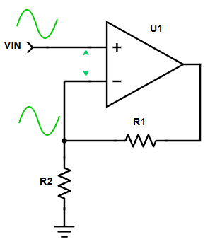
An example is the circuits above, a standard op-amp amplifier, non-inverting. The input voltage is swinging by say 500mV. 500mV sounds pretty big compared to what we were talking about earlier. But look at the op-amp circuit overall. It has negative feedback, so its inputs stay almost exactly equal. When the positive input goes up by 500mV, the negative input is also going up by very close to 500mV. We can even zoom in, inside the op-amp and see the inputs.
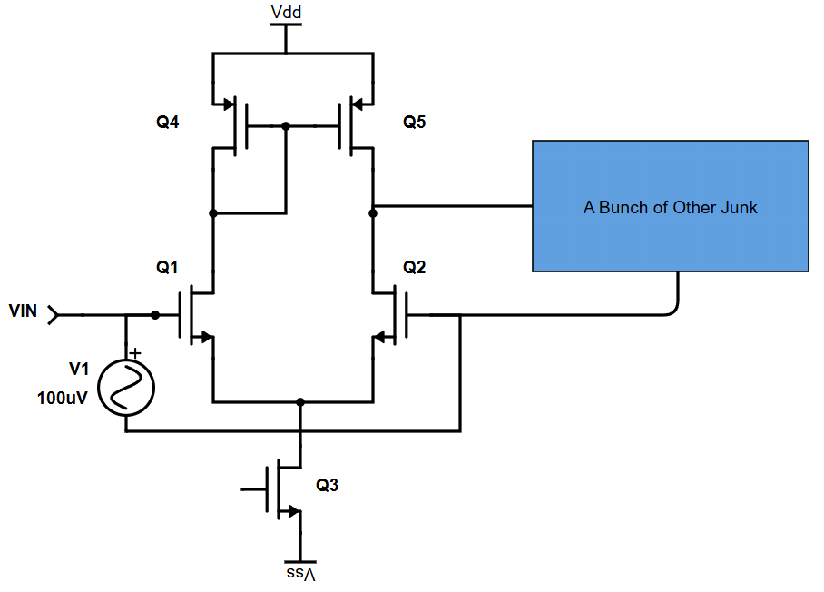
Q1 is the “PLUS” and Q2 is the “MINUS”. There’s all sorts of other stuff happening, but at a basic level Q1 and Q2 do like 90% of the work in an op-amp and are where most of the focus goes. Because of negative feedback, whatever Vin does to Q1, the “bunch of other stuff” takes the amplified Vin and sends it to Q2, which inherently almost cancels out the effect of Vin on Q1. Almost. The op-amp “sees” a difference at its inputs, at Q1 and Q2, but never that 500mV. As far as the op-amp is aware, both its inputs are almost equal, with just tiny changes. Tiny changes. Small signals.
5. Small-signal analysis doesn’t apply to switching circuits
This is probably the biggest misconception. We’ve so far talked mostly about linear applications, or linearizing non-linear devices, and how even systems that experience wide swings overall may be made up of components that each only see small changes, but what about something that truly is switching over and over? What about something like a buck converter or a phase-locked loop (PLL)?
This is the basic basic schematic for a buck converter. It exploits the fact that inductors can have their voltage switch instantaneously, but not their current, while capacitors can have their current change instantaneously, but not their voltage. For a further physical explanation of why this is, see our previous post on inductor/capacitor energy storage. By rapidly switching the inductor’s input, you get this effect where the inductor is trying to rapidly switch its output as well, but can’t because the capacitor opposes changing voltage. The capacitor tries to please the inductor by rapidly pulling current, but can’t because the inductor opposes changing current. They enter this sort of stalemate, a strange equilibrium where even though things are switching, the output remains a relatively steady voltage.
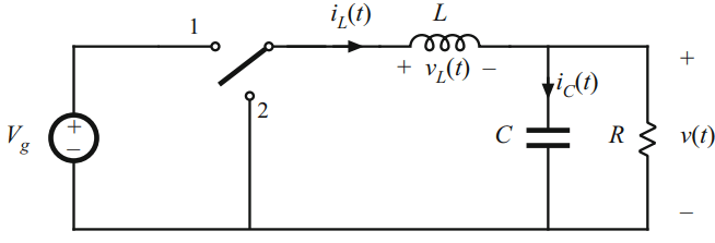
That output voltage is dependent on the ratio of switching, the duty cycle. If the inductor is connected to node 1 for 80% of a 200kHz square wave, and to node 2 for the other 20%, we call that an 80% duty cycle, a variable simply denoted “D”. The switches are transistors that are in fact switched, on and off, very quickly in what’s called Pulse Width Modulation (PWM). There is no “small signal” that they see, no abstract condition, they really are turned fully on and fully off with (ideally) no in between state, no metastability crap. So why are we even talking about this?
I’m going to throw a wrench into this situation. If you just set D and forget about it, the output will not be what you want. The resistor in this schematic is a stand-in for any load. It could be a motor, it could be a laser, it could be a computer chip. Those loads are not a fixed resistor, they’re rapidly pulling different currents because they themselves may be switching on and off. A different current means that that “immovable capacitor vs unstoppable inductor” equilibrium is thrown out of whack.
I’m going to do the opposite of throwing a wrench into this situation; I’m going to throw another wrench (but one for fixing stuff and not throwing at your face during a game of dodgeball). Feedback! That should always be your first instinct as a designer of any system. If you want something to be one one way, but it ain’t, see if you can solve it with feedback.

This is a slightly more detailed – though still simplified believe it or not – schematic of a buck converter. Notice the block labeled “feedback control”. What we do is measure the output voltage with a voltage divider, filter it, and then generate the PWM duty cycle, which switches the transistors on and off. I’m now unfortunately going to have to throw a third goddamn wrench into this, another one of the bad ones too. Any time you have feedback, you also have potential instability. For most amplifiers this is already unwanted, but for a power supply that is supplying potentially kilowatts, instability could literally mean fires and explosions. In these situations it is absolutely imperative we be able to analyze, predict, and solve any possibility of instability.
We’d like to use our normal tools like loop gain and phase margin but this is so non-linear, on, off, on, off, what does it even mean to create a Bode plot of a square wave? We abstract it and treat the duty cycle itself like a voltage. Aha! After all the duty is really what we’re controlling, the voltages at the switches are flipping between VDD and GND. We can replace the switches with linear elements that model how the output voltage changes with small changes to the duty cycle.
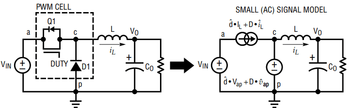
The same way that we turn non-linear transistor amplifiers into voltage dependent current sources, we can turn these switches into duty cycle dependent sources, and that duty cycle is controlled by a totally linear feedback loop, so we’re back to true small-signal analysis and all of our same rules like input/output impedance and Bode plots and phase margin and damping all apply!
To learn more about this type of small-signal modeling, I recommend this app note from Analog Devices, on stabilizing/compensating switching power supplies, as well as this thoroughly in-depth app note from Texas Instruments about PLL design and loop filters.
Epilogue

This is a slinky. The whole slinky is bending uuuppppp and down. The entire slinky is moving down a full step, and then a full step, and then a full step. But each rung of the slinky only sees a small change. Transistors are like this too, they can all together have this huge effect while individually doing small things. That’s why we do small-signal analysis, to understand where it sits on each rung of the slinky.