Hi everybody! So today I wanted to show everyone a circuit that I designed and mostly wanted to coin the name for out of a sense of Bob Widlar-esque narcissism, since I couldn’t find anything like this while doing research.
The Task
The project I was tasked with was to take our programmable current source and convert it to a single supply design. This is the original design.
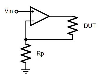
It’s remarkably simple yet effective. By picking the right parts, we could get great performance in terms of noise and temperature drift down to 100nA. A DAC goes to the non-inverting input, flips between +1V and -1V, and the op-amp puts out enough current to keep its inverting input at +1V and -1V. That current goes through the DUT (device under test), which produces a voltage we can measure elsewhere and get an accurate 4-wire resistance reading.
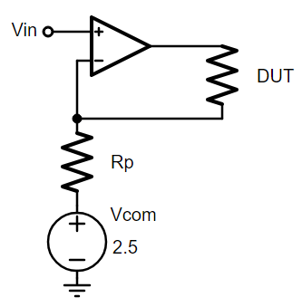
With a single supply, we can’t flip between +1V and -1V, negative voltages don’t exist in our vocabulary! What we can do is *shift* the whole circuit up. Instead of that resistor going to 0V (ground), it goes to 2.5V. Instead of flipping between +1V and -1V, the DAC flips between +3.5V and +1.5V. As far as the op-amp and resistor is concerned, that’s the same as putting +1V and -1V across Rp, which results in bipolar current through the DUT! Even though the voltages are all positive, the current through the load can go positive or negative!
Aside: Thermal EMF
Something to clarify before we go on, the reason bipolar current is so important is because of what’s called “thermal EMF”. This circuit is designed for temperature sensors working under 1 Kelvin (they’re specced for 0.4 Kelvin but we’ve used them for as low as 0.01 Kelvin). When a material has a temperature difference across it, it turns into a thermocouple and generates its own voltage. You can see this at room temperature too, BNC connectors in particular have a terrible thermal EMF problem at lower frequencies, but it’s much more apparent at these lower temperatures and weird materials. To get rid of it, you have to reverse the current and average it out. This is why Keithley’s picoammeters and nanovoltmeters have “delta mode”, to reverse and average out thermal EMF. If you’d like to know more, the Keithley 6221 and Keithley 2182A manuals, as well as our favorite friend The Keithley Low Level Measurements Handbook are great sources of info on this.
So okay, back to our little dinky circuit, what’s the problem here? For all you beginners and intermediaries out there, this is the part to pay attention to. From a circuit perspective, there’s nothing wrong here. Single supply, low power, great accuracy and so on. Okay but what’s the load? What’s the thing we’re actually delivering that current to? WHAT’S THE APPLICATION?!!
Cual Es La Aplicacion?
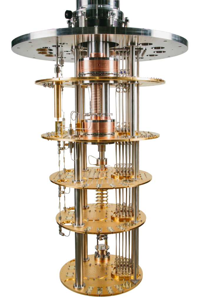
In this application, the load is a tiny zirconium-nitride-something thin film NTC resistor called Cernox in a near-absolute-zero-Kelvin environment in a dilution fridge, connected through meters of 30-34AWG beryllium wire because copper is too brittle at that temperature. In this application, noise is not just unwanted signal, noise is concrete power, and power is heat. We’re working with superconductors, which have a sudden jump in resistance from 0 to finite, so if we inject too much heat, we break it out of superconductor conditions and the whole system becomes hot in an instant. That’s not good, it literally takes days to pump a system back down under 20K. The circuit we’re making is also grounding and shielding the entire dilution fridge, which means that every power rail affected the whole system.
The issue here is that by switching the current back and forth, the COMMON MODE voltage of the sensor is also flipping back and forth. What does that mean? If the input to the op-amp is +3.5V, then because of op-amp feedback, one end of the sensor is also +3.5, and the other end is something above that (per Ohms Law). Then once the DAC outputs +1.5V we have the reverse current we want, but — gasp! — now the sensor’s negative terminal is tied to +1.5V, and the other end (at the op-amp output) is +1.5 minus Ohm’s law? So one terminal of the DUT is being flipped between +1.5V and +3.5V, and the other terminal is being flipped between 1.5-I*R and 3.5+I*R.
If you think about the temperature sensor as a see-saw, sure the see-saw is swinging the way we want, but the fulcrum is being tugged back and forth, and that’s no bueno! Even though all we care about is the voltage *across* the sensor, the actual voltages themselves cascade down the line.
Smokestack Lightning
My colleague suggested I start with the Howland current source. The idea behind the Howland current source is that it’s a difference amplifier (meaning it outputs the difference between two inputs), but the output is a current instead of a voltage. Below is a diagram of the typical Howling Wolf — I mean Howland current source.
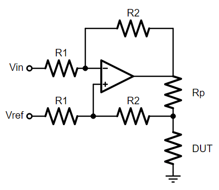
Looks like a rat’s nest at the bottom there don’t it? In analog design, we say “if it looks messy it probably is”. Remember how I said that the difference is output, and that output is being put across the load? With the regular Howland that load is coming back to the input, so the first step is to keep ’em separate. Below is what’s called the “modified Howland source”.
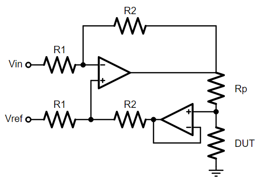
Now the voltage at the end of Rp is buffered. Now the voltage across Rp (which determines the current) is dependent on R2 and R1, but not the other way around. The op-amp and R2/R1 put a +1V or -1V across Rp. We can switch out Rp’s to get different currents, and that current goes through the DUT. That buffer ensures it’s a one way relationship, so all the current through Rp goes through the DUT, and it doesn’t create an error in the R2/R1 differential amplifier. Now I’m gonna show you the final circuit. It’s a simplified circuit, you’ll have to adjust this to your specific application based on stability and current.
Remember, the goal is to get a (1) bipolar current source (2) on a single supply (3) with a stable common mode.

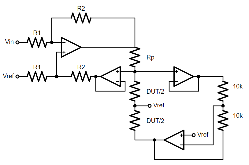
This is the Bipolar Shrid Pump. It can provide bipolar current off a single supply while keeping the common mode of the DUT stable. The idea is that the DUT is the star of the show, and the circuit should dance circles around it rather than hoping the DUT fits the circuit.
The entire block on the left is the Modified Howland Pump we talked about, but we now have complete control over the “see-saw” and the “fulcrum” of the DUT. The reference point is no longer a single voltage, it’s based on the voltage *across* the DUT.
We sense and control the voltages on either end of the DUT, based on the current through the DUT, but that control circuit on the right makes sure that the “fulcrum” is centered around Vref. That op-amp on the right keeps its positive terminal centered at Vref, and it has two equal resistors above and below that represent the “top half” and “bottom half” of the DUT. So the temperature sensor, the NTC, the DUT, is treated exactly the same, its positive and negative terminals are held in such a way that its center, its fulcrum is held at Vref, 2.5V. I designed it so that the two resistors on the right would be a metaphor for the DUT on the left, and I wanted it to be centered around a Vref of 2.5V. Below illustrates that point.
Important to note again, 2.5V is what the circuit is holding the outer shell of the dilution fridge at, so if the temperature sensors are centered around 2.5V (meaning the plus and minus nodes average out to 2.5V) that’s less leakage, which is important when we’re talking about pico and nanoamps. And because we’re not wiggling that middle point around, that’s less “common mode modulation” into our own voltage-sensing circuit on the other side. This is really important for this application, you can very clearly see the common mode problems in the data. The application, the specific situation, gave us our requirements and we used creativity to design a circuit around those requirements. Yay!!
I hope that gives some of you an idea of what the design process is like. Keep in mind that this took weeks of pacing back and forth like a madman to come up with a design, with lots of great input from colleagues (mostly Harry Reichard if we’re being honest, thanks Harry!) and longer to get it right in implementation. This schematic shows only op-amps and resistors, but in practice there’s a bunch of stray capacitances and inductances that caused a lot of problems to solve. For any young hardware engineers, be patient, it takes a long time to build something useful in this field. If you’re successful it won’t look impressive. Or at least that’s what I tell myself every morning in the mirror.
Anyway, here’s a cat picture, probably right after eating a bunch of lasagna: