Any first year EE student has heard this phrase. In a capacitor, voltage lags current. In an inductor, voltage leads current. This makes sense from a mathematical point of view. You take the Laplace transform of their respective differential equations, and you find that their impedances come out to 

Let’s consider a few things first. What is voltage? What is current? Voltage is defined as the work required to move a unit of charge between two points in an electric field. Current is defined as the average current density through a surface. Voltage we can think of as sort of electric pressure, and current as electric flow. Voltage is across points, while current is through surfaces.
Can we have a current with no voltage drop? Sure! The wires between two resistors (ideally) have no voltage drop but current can go through them. Can we have a voltage drop with no current? Sure! Open circuits are just this, they hold voltage between two points but no current flows. With this understanding, let’s look at our three main components.
Resistor: in phase
With resistors, they need a voltage for current to flow, and the relationship between them is given by Ohms Law. No voltage, no current. When you apply a voltage, a proportional current will flow through. This relationship is bidirectional; if you force a current through, a voltage drop will occur whether you like it or not. Because the relationship is directly and immediately proportional, if you input a voltage sine wave, the current will follow it exactly in time at all points without delay.

Capacitor: voltage lags current
This is not the case with a capacitor. A capacitor is specially constructed and isn’t all just a single conductor. It switches from conductor to dielectric to conductor. Conductors and dielectrics differ in how electrons move. In a conductor, electrons are free as the wind, all they need to move is some voltage to push them wherever you please. In a dielectric, the electrons are bound to the nucleus. Unless you provide a very large amount of energy to break that bond, they are tethered. If you try to apply a voltage, for a very short amount of time the dielectric will look like a short and there will be no voltage drop across the device. Charge carriers are not actually moving through the conductor-dielectric boundary, they can’t do that. Instead you’re packing more and more positive charge onto one side, thereby changing the voltage. What this bunched up concentration of charges is doing is polarizing the individual atoms in the dielectric. That motion of charges, believe it or not, is a form of current. The polarization in the dielectric also pushes and pulls charges on the plate on the other side, thus allowing current on one plate to generate current on the opposite plate.
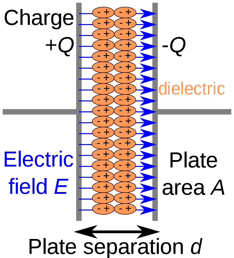
Over time you pull the electrons and push the protons as far as they will go from their nucleus, and subsequently pushing protons on the other conductor. But once that happens, then what? Current can no longer go through, we’ve pulled the electrons and pushed the protons as far as they will go, creating a charge separation and thus a voltage across the capacitor. So unlike a resistor where pushing a current creates a voltage drop at exactly the same time, when you push a current through a capacitor, it first has no voltage drop (just like a wire) and only after some time does a voltage appear across it. You can instantaneously start to pull electrons and push protons, but you cannot instantaneously push/pull them all the way. If you input a voltage sine wave, the current will appear as a cosine wave i.e a sine wave shifted forward in time. Voltage lags current.
Inductor: voltage leads current
The same can be done with inductors. You can take a voltage source and put it across the terminals and that voltage will instantly appear. But unlike a straight wire, we now have a curled up wire. Due to the laws of electromagnetics, the moment you even begin trying to push current through it, the loops will produce a magnetic field, and that magnetic field will produce a current that opposes the current you’re trying to push (Lenz’s law). We have a voltage across two terminals, but no current flowing through, just like an open circuit. It doesn’t oppose it 100%, there’s always losses, so more and more current will be able to go through as time passes and the magnetic field grows as it tries to fight it. It eventually reaches a steady state. Magnetic fields don’t produce current, changing magnetic fields do.

So the magnetic field hits its maximum density and then stays there and stops producing an opposing current. The only thing that makes wire loops special is the changing magnetic field. With a constant magnetic field, that loop is now no different than a piece of wire, which now means there’s no voltage across but there is current going through. In this case we applied a voltage, and then some time later a current appeared through it. It’s like pushing a car in neutral. Hard to start, easy to move once it gets going, and then hard to stop. You can instantaneously start to generate a magnetic field, but you cannot instantaneously create the maximum magnetic field. If you input a voltage sine wave, the current will appear as a sine wave shifted back in time. Voltage leads current.

2 thoughts on “Voltage lags current: a physical interpretation”